What a Truss Does
A truss converts a bending problem into a set of compression and tension problems. A solid timber beam long enough to span a 40-metre river would be impractically heavy and prohibitively expensive. A truss of the same span uses far less material because it divides the load into axial forces — members either push (compression) or pull (tension) along their length — rather than bending across it.
Timber handles compression well and handles tension acceptably when the grain runs continuously along a member. Iron handles tension far better than wood. This material difference shaped the design of every covered bridge truss system: builders gradually moved tension work into iron rods and reserved timber for compression chords and diagonals.
The Howe Truss
William Howe patented his truss design in 1840, and it became the dominant form for Canadian covered bridges throughout the second half of the 19th century. The Howe configuration places timber diagonal members in compression and uses vertical iron rods in tension. The combination was practical for two reasons: iron rods were easier to ship to remote building sites than heavy timber, and they could be tensioned with nuts after installation, allowing the truss to be tuned in the field.
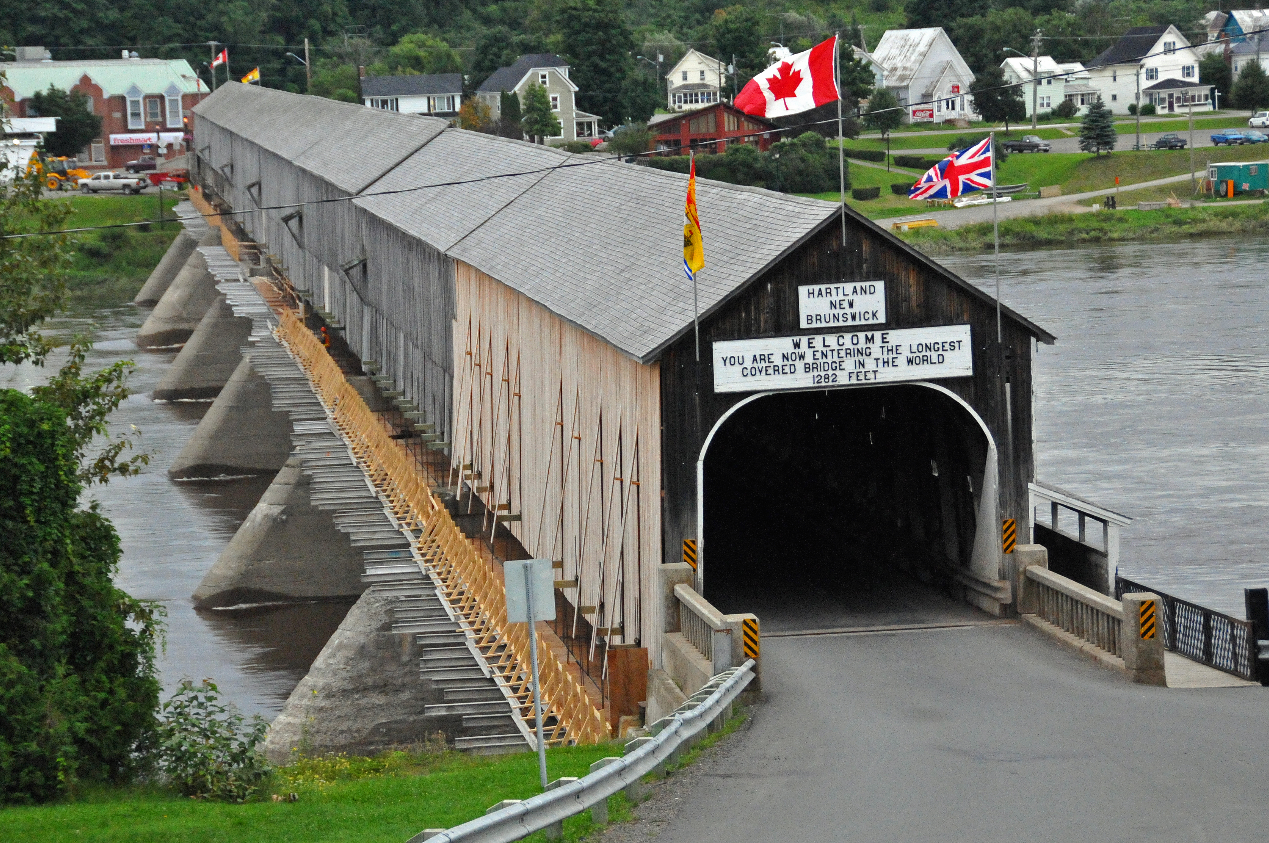
The Hartland Covered Bridge in New Brunswick — the longest covered bridge in the world at 391 metres — uses Howe truss construction across its seven spans. Each span runs approximately 55 metres and was built using local white pine and spruce. The iron rod assemblies in Hartland have been replaced or supplemented during successive rehabilitations, but the timber chord members in several spans are original to the 1901 construction.
Span capacity for a Howe truss in covered bridge applications ranged from roughly 30 to 75 metres, depending on the timber species, member dimensions, and the quality of the iron hardware. New Brunswick bridge builders consistently used the upper portion of this range.
The Burr Arch Truss
Theodore Burr received a patent for his combined arch and truss design in 1817. The Burr configuration superimposes a long-timber arch — running from abutment to abutment beneath the truss chords — on a multiple kingpost truss. Under normal live loads, the arch carries the majority of the force, with the truss acting as a stiffening frame. Under heavy or concentrated loads, both systems engage simultaneously.
The practical advantage of the Burr system was redundancy. If a truss panel was damaged — by rot, impact, or overload — the arch continued to carry traffic. This made the Burr design particularly forgiving in an era when bridge inspection was informal and repairs were sometimes deferred for years.
The long arch chord in a Burr bridge is typically a continuous timber member made from a single tree or joined in scarf with wooden keys. Finding straight-grained timber long enough for a full arch chord became progressively more difficult as the 19th century advanced and nearby forests were harvested. This supply constraint contributed to the Howe truss gaining preference over the Burr design in later decades.
The Town Lattice
Ithiel Town's 1820 lattice design replaced heavy timber chords and posts with a dense diagonal lattice of relatively thin planks, typically 50 mm by 250 mm, bolted at every intersection. The lattice distributes loads through many small members rather than concentrating them in a few large ones.
Town's design had one significant commercial advantage: it could be built by unskilled labour. There were no complex mortise-and-tenon joints, no iron rods to tension, and no large timbers to move into position. A crew of workers with standard carpentry tools could assemble a Town lattice span in a fraction of the time required for a Howe or Burr bridge.
The limitation was span. Town lattice bridges worked efficiently up to about 40 metres; beyond that, deflection under load became noticeable and the bolted connections at lattice intersections required frequent attention. Most Town lattice bridges in Canada are found in Quebec and Ontario, where river crossings were shorter than the wide spans of the Saint John River system.
Queenspost and Kingpost Trusses
The queenspost truss is among the oldest timber frame configurations used in bridge construction. Two vertical queen posts support a horizontal top chord, with diagonal braces running from the base of each post to the ends of the span. A central compression strut between the posts keeps the top chord from buckling laterally.
Queenspost bridges were suited to spans between 12 and 25 metres — the range typical of smaller rural crossings. They were straightforward to build and required no iron hardware beyond the connection bolts. Many early Ontario and Quebec covered bridges used this form, and several remain in provincial parks and heritage designations.
The kingpost truss, with its single central vertical post, was the form used for the shortest crossings — footbridges and light vehicular spans under 12 metres. It is the simplest statically determinate truss and served as the introductory form through which builders learned the principles of triangulated load distribution before tackling more complex configurations.
Lateral Bracing and Wind Loading
The enclosure that defines a covered bridge — the roof and siding — also serves a structural function. The boarding on the sides of the bridge acts as a shear diaphragm, stiffening the structure against lateral loads from wind and the dynamic forces generated by moving vehicles. Without the enclosure, a long timber truss bridge would require separate lateral bracing frames, adding material and cost.
This relationship between the enclosure and the lateral stability of the structure is one reason why removing or replacing the siding on a historic covered bridge must be approached with structural care. The boarding is not merely cladding; it is part of the load path.
Roof framing in Canadian covered bridges typically uses common rafter construction over a ridge board, with the rafters bearing on the top chords of the truss. The roof surface sheds snow and rain away from the deck and structural members below, protecting the timber from the moisture cycling that accelerates decay.
Material Selection and Its Limits
Builders in 19th-century Canada selected timber species based on what was locally available. White pine, eastern spruce, and Douglas fir (in western Canada) were the primary structural species. Each had different strength characteristics, different rates of shrinkage, and different susceptibility to decay fungi.
White pine was prized for its straightness and workability but is softer than spruce and more susceptible to decay when moisture infiltrates connections. Eastern spruce is stiffer and more resistant to decay but harder to work and more prone to checking — surface cracks that develop as the wood dries after installation. Both species performed adequately when the enclosure kept the structural members dry; both deteriorated rapidly when the enclosure was compromised.
The iron hardware — tension rods, connection bolts, bearing plates — was sourced from foundries and hardware suppliers in larger towns. The quality varied, and corrosion of iron hardware has been a contributing factor in the structural decline of many surviving covered bridges.
Sources and Further Reference
The structural analysis in this article draws from the following published references:
- HistoricBridges.org — comprehensive database of surviving covered bridge structures in North America, with documented truss types and span dimensions.
- Allen, Richard Sanders. Covered Bridges of the Northeast. Brattleboro: Stephen Greene Press, 1974.
- McKee, Brian J. Historic American Covered Bridges. New York: ASCE Press / Oxford University Press, 1997.
- Parks Canada — Hartland Covered Bridge National Historic Site